
COMPANY: TL Offshore
PROJECT TITLE: Muda Field Development Project
CLIENT: CPOC
LOCATION: Thailand/Malaysia Border
YEAR: 2008
VESSEL: Derrick Lay Barge (DLB) Lewek Champion
AUTHOR SCOPE OF WORK: Installation of 4 legged Platform – MDA, MDB, MDC, JKA & MDLJ (Jacket & Topside) & 1 no of 8-legged Platform – MDPP (Only Jacket)
MY INVOLVEMENT:
INTRODUCTION
Widely known by the abbreviation JDA, the wedge-shaped Malaysia-Thailand Joint Development Area (JDA) covers an area of about 7,250 sq. km., formed by overlapping continental shelf claims between the two countries. The heart of JDA lies about 180 km from the shores of Pattani province, 260 km from the shores of Songkhla, and 150 km from Kota Bahru in Kelantan State of Malaysia.
Phase I primarily involved the installation of the Muda Processing Platform (MDPP) and living quarters platform (MDLQ), five wellhead platforms namely Muda-A (MDA), (MDB), (MDC), (MDD) and Jengka-A (JKA), the leased FSO Ratu Songkhla with a storage capacity of 550,000 barrels, a flare tripod, and interconnected subsea pipeline.
The engineering, procurement, construction, installation and commissioning (EPIC) contract for the phase I was been awarded to SapuraKencana Petroleum Berhad (SapuraKencana).
Sembcrop Marine Offshore Platform Pte. Ltd was the engineering, procurement, construction and commissioning (EPCC) contractor for the MDPP, whereas the jacket was supplied by Malaysia Marine and Heavy Engineering (MMHE).
The EPCC contractor for the MDLQ, flare tripod and three bridges was Sapura-Kencana, the detailed engineering works for the MDLQ were performed by BHIC Petroleum and the construction engineering, fabrication, loadout and sea-fastening of the MDLQ jacket and flare tripod were performed by CUEL. The wellhead platforms under phase I were fabricated by Oilfab.
Transport and float-over installation of the MDPP platform were performed by Dockwise. The heavy-lift installation of the MDDP’s jacket was performed by Sapura Acergy.
Platform General & Jacket Details
| Platform | Muda-A (MDA) | Jengka-A (JKA) | Muda-C (MDC) | Muda-B (MDB) |
| Platform Location | 277 825 E 839 635 N | 309 675 E 829 500 N | 274 970 E 839 080 N | 270 410 E 838 000 N |
| Orientation | 0º from True North | 0º from True North | 0º from True North | 0º from True North |
| Water Depth | 200.7 ft (61.2 m) | 206.15 ft (62.85 m) | 201.12 ft (61.3 m) | 198.5 (60.5 m) |
| Jacket Description | Four-legged | Four -legged | Four -legged | Four -legged |
| Jacket Installation | Lift-off, lower and rotate in the water, single block upend in water and place jacket on seabed using flooding system. | Lift-off, lower and rotate in the water, single block upend in water and place jacket on seabed using flooding system. | Lift-off, lower and rotate in the water, single block upend in water and place jacket on seabed using flooding system. | Lift-off, lower and rotate in the water, single block upend in water and place jacket on seabed using flooding system. |
| Installation Barge | DP DB Lewek Champion | DP DB Lewek Champion | DP DB Lewek Champion | DP DB Lewek Champion |
| Jacket lift weight | 550 MT/606.65 ST excluding, rigging and rigging platform | 550 MT/606.65 ST excluding, rigging and rigging platform | 520 MT/573.3 ST excluding, rigging and rigging platform | 515 MT/567.78 ST excluding, rigging and rigging platform |
| Jacket Component | Leg A1, A2, B1 & B2(5 section of piles) | Leg A1, A2, B1 & B2(5 section of piles) | Leg A1, A2, B1 & B2(5 section of piles) | Leg A1, A2, B1 & B2(5 section of piles) |
| Jacket Work Point Dimensions | 10300 mm x 9144 mm at EL(+) 7000 mm | 10300 mm x 9144 mm at EL(+) 7000 mm | 9144 mm x 9144 mm at EL(+) 7000 mm | 9144 mm x 9144 mm at EL(+) 7000 mm |
Deck Details
| Platform | Muda-A (MDA) | Jengka-A (JKA) | Muda-C (MDC) | Muda-B (MDB) |
| Deck Description | Drilling Platform | Drilling Platform | Drilling Platform | Drilling Platform |
| Deck Installation | Lift-off and set onto jacket leg. | Lift-off and set onto jacket leg. | Lift-off and set onto jacket leg. | Lift-off and set onto jacket leg. |
| Installation Barge | DP DB Lewek Champion | DP DB Lewek Champion | DP DB Lewek Champion | DP DB Lewek Champion |
| Deck lift weight | 836 MT / 922.11 ST excluding contingency | 916 MT/1009.71 ST excluding contingency | 670 MT / 738.68 ST excluding contingency | 675 MT / 744.18 ST excluding contingency |
| Designed Deck Elevation (TOS) | Leg Stabbing Point EL(+) 8400
Sump Deck EL(+) 9500 Cellar Deck EL(+) 14500 Main Deck EL(+) 20500 |
Leg Stabbing Point EL(+) 8400
Sump Deck EL(+) 9500 Cellar Deck EL(+) 13500 Main Deck EL(+) 20130 |
Leg Stabbing Point EL(+) 8400
Sump Deck EL(+) 9500 Cellar Deck EL(+) 13500 Main Deck EL(+) 19500 |
Leg Stabbing Point EL(+) 8400
Sump Deck EL(+) 9500 Cellar Deck EL(+) 13500 Main Deck EL(+) 19500 |
Installation Tolerance
| a. | Jacket not attached to existing platform | |||
| 1. | Center jacket tolerance | : | Within 15m radius from design. | |
| 2. | Orientation | : | (±) 4° from design heading | |
| b. | Jacket attached to existing platform | |||
| 1. | Lateral offset | : | ± 0.5m | |
| 2. | Longitudinal distance between jacket and existing platform | : | ± 0.5m | |
| 3. | Orientation | : | (±) 2° from design heading | |
| c. | Elevation difference between lowest and highest elevation. | |||
| 1. | 3 pile jacket | : | Within 50mm | |
| 2. | 4 pile jacket | : | Within 75mm | |
| 3. | 6 pile jacket | : | Within 150mm | |
| 4. | 8 pile jacket | : | Within 200mm | |
| 5. | Maximum allowable slope | : | Slope of 1:100 across the jacket legs | |
| d. | Footprint survey | |||
| 1. | Jacket Foot Print Survey | : | 25m radius (By ROV) | |
FIELD LOCATION

LOAD-OUT & TRANSPORTATION
The four (4) platforms (MDA, JKA, MDC & MDB) comprising of Jacket, Main Piles, and Topside have been fabricated by the following fabricators:
# 2, Jalan Sungai Chandong 13
Pulau Indah Indsutrial Park
42920 Pulau Indah
Selangor, Malaysia
The jacket had a temporary rigging platform pre-installed at the fabrication yard to accommodate the jacket side lift and upend slings, which was pre-rigged at the fabrication yard. The fabricator alsoe pre-rig the Topside rigging. The details on pre-rigging arrangement for each platform are outlined in its respective procedure.
The four (4) platforms components will be loaded out and transported to the installation site on the following transportation barges:
| Platform | Component | Transportation Barge |
| MDA | – Jacket
– Main Piles – Transition Piece – Boat Landing – Topside |
|
| JKA | – Jacket
– Main Piles – Transition Piece – Boat Landing – Topside |
|
| MDC | – Jacket
– Main Piles – Transition Piece – Boat Landing – Topside |
|
| MDB | – Jacket
– Main Piles – Transition Piece – Boat Landing – Topside |
Sealink Pacific 287
282L x 90W x 18D
|
Detailed review of all components and material loaded out were conducted and checked against the loadout list in each platform Loadout Coordination Manual for Jacket and Topside”.
The transportation barge arrived at the fabrication yard with all tanks de-ballasted (empty). A gas free check of all ballast tanks was carried out upon arrival of barge at the fabrication yard’s wharf.
- MDA
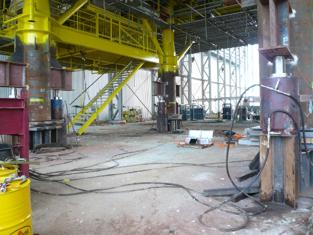
Deck Weighing of MDA Deck:


At each of the topside leg, 2 load cells on each side is placed
Flooding Valve Trial Fit
was difficult to turn during trial. It was my first loadout witness so did not bother and had problem later offshore
Sometimes problem occur is leaking of Hydraulic oil
I was stationed in Laem Chabang for 1 month supervising the loadout of MDLJ. Main thing to consider
MOBILIZATION
DLB Lewek Champion was used. The vessel mobilization was performed at Pasir Gudag, Johor Bahru.
JACKET INSTALLATION
PRE-INSTALLATION SEABED SURVEY
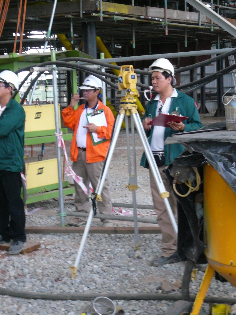
Prior to jacket lift and set, the surveyors verifed the DGPS input parameters and accuracy of the system and signed off by the Field Engineer.
The primary survey positioning system using offsets was used. A secondary positioning system, using offsets was also be used as a back-up to the EDM. Offsets will be measured and marked on the side of the barge from the survey station on the derrick barge. Tugger lines were connected to the face of jacket closest to the barge. A mark was painted on each of the tugger line based on the offset between barge side and face of jacket. This is to orientate the jacket to the correct angle before setting down. The offsets was determined by the surveyors and verified by field engineers.
On seabed survey upon barge arrival at field, ROV was deployed within 100m radius of the proposed platform location to ensure there are no obstructions, limitations or debris that will interfere with jacket setting.
JACKET SIDE LIFT
With all preparations completed, the derrick barge commenced the jacket lift as per below sequence.
- Final setup for derrick barge was determined and material barge was secured.
- Obtained MWS approval prior to cut seafastening (first 50%).
- Transferred welders to the barge and commence cutting tie-down seafastening up to 50%.
- Transferred riggers to the rigging platform via personnel basket to prepare sidelift rigging.
- Positioned main block over center of lift and check radius.
- Connected side lift rigging to main block and took up slack.
- Connected air tugger control lines to top jacket brace or suitable points.
- Obtained MWS approval prior to cut the remaining seafastening
- Cut the remaining 50% tie-down seafastening and obtained MWS approval prior to sidelift the jacket
- Completed cutting seafastening and took up the weight of the jacket with the Derrick Crane.
- Lifted-off jacket from material barge. Towed away material barge from derrick barge.
Note: Prior to lift jacket, all personnel will be transferred off the jacket rigging platform.
- Lowered jacket into water until lifting slings became slack and jacket is floating freely.
- Secured jacket to stern side of the derrick barge using soft line.
- De-rigged sidelift riggings and remove sidelift rigging platform.
JACKET UPEND
- With jacket secured at stern side of derrick barge upending slings to the derrick crane were connected.
Safety Notes: Safety harness to be taken and fastened by personnel climbing to jacket top brace to access flooding valves. All personnel involved must wear work vest.
- Attach control tugger lines to the upending shackles on jacket legs.
- Remove securing lines from jacket to barge.
Safety Notes: Have earplugs and eye protection available for use during jacket leg venting.
- Re-positioned the jacket utilizing tugger boats.
- Commence the detailed upend procedure.
- Personnel was transferred to the jacket by a personnel basket when jacket at about 89° pitch angle to open the flooding valves. Flooding valves is designed for man operated.
- Jacket upending was performed in accordance with procedure. The designated hook load is was not to be exceeded thus preventing the possible occurrence of the jacket emerging excessively from the water and becoming unstable. To prevent such incident, hook load should stay in the range as per recommended upending procedure.
JACKET SETTING
- After the jacket is upended, jacket was positioned to design location.
- Transferred Surveyor to top jacket to install prism onto the dedicated handrails socket and measuring tapes.
- Lower jacket to seabed whilst surveyor crosschecks jacket final position and orientation.
- In the event the jacket tilt to one side after setting, estimates the gain after the jacket is leveled.
JACKET SECURING
- Secured jacket with polypropylene rope tied loosely to the capstan
PILE INSTALLATION
Barge set-Up
The pile barge will be brought alongside to derrick barge for lifting of all pile sections a after the platform has been secured. All piles on material barge will be upended directly on material barge using whip block.
Pile Driving Hammers
Hydraulic driven hammer MHU-270T and MHU-500T was be used for pile driving activities (whichever is applicable) depending on site condition.
The allowable stick-up lengths for the hammers are specified in Table 4.2-1 below.
Table 4.2-1
Pile Driving Hammers Specifications
| Hammer Type | MHU 270T | MHU 500T |
| Number Provided | 1 | 1 |
| Max. net impact energy – above water (kNm)
Min. Net impact energy (kNm) Blow rate at max energy possible (kNm) |
297
27 50 |
550
50 55 |
| Average operating pressure (Bar) | 250 | 230 |
| Total Weight (MT) | 38 | 80 |
Table 4.2-2
ALLOWABLE PILE STICK UP LENGTHS
(with respect to EL (+) ## mm level)
| Section | Stick Up Length (m) (MHU270T) | Actual Stick Up Length (m) (MHU500T) |
| P2 | ||
| P3 |
Note: Expected self penetration P1 ## m
- Length shown of section P2, P3, P4 and P5 does not include stabbing guide length.
- Lengths and weights shown include cut-off allowance. Refer to 4.1-1 for the pile make up details.
- Jacket leg diaphragms will be punctured using piercing tools during pile installation.
- Pile rigging for Internal Lifting Tool (ILT) as shown in Fig 4.1-2a & Fig. 4.1-2b.
- All P1 and P2 had been fitted with stoppers as per Fig. 1-1.
PILE HANDLING
PILE INSTALLATION SEQUENCE
PILE MONITORING
Pile Monitoring
Pile monitoring will be done as detailed below:
1) Pile monitoring will be conducted on 2 pile legs of the last 2 add-on (P2 & P3).
- In additional to pile monitoring, a re-drive test (min.0.3m and max 1.0m) will be done on one of P3 pile (minimum 24hours set-up time).
REFUSAL CRITERIA
- Pile Driving Refusal Criteria
A driving refusal is defined as the point at which the pile driving resistance is:
| Note:
300 blows per foot (0.3m) for five consecutive feet (1.5m) or 800 blows for one foot (0.3m) of penetration. (This definition applies when the weight of the pile does not exceed four times the weight of the hammer ram. If the pile weight exceeds this, the above counts are increased proportionally, but in no case shall they exceed 800 blows for six inches (152 mm) of penetration). Refer to API RP2A-WSD
|
When driving has been interrupted for one hour or more, the refusal criteria above shall not apply until the pile has been advanced at least one foot (0.3m) following resumption of pile driving. However, in no case shall the blow count exceed 800 blows for six inches (152mm) of penetration.
Should refusal be encountered, Contractor will consult with Company representative for necessary remedial action.
JACKET LEVELING
- Jacket Leveling Methods
During installation, a combination of stabbing and sequential driving will be used to maintain jacket level within tolerance. If jacket level is out of tolerance while driving P2 or P3 pile section, the following procedure will be followed.
- a) Jacking Method
- After confirmation of “out-of-level”, install jack pad at target leg/pile and arrange either to jack-up or jack-down.
- Position the hydraulic jack at jack-pad. Refer to Fig 4.3.4-1 and Fig 4.3.4-2.
- Jack the jacket leg approximate height of “out-of-level” and hold.
- Confirm jacket within level.
- Weld out the dogs to pile, sized appropriately to load.
- Release hydraulic jack load.
- Re-check level.
- Remove jack pad from jacket leg.
- b) Direct Uplift using Padeye
- Another option for “out-of-level” tolerance by using upending padeye pick up one or two (as required) jacket upending slings with required derrick crane block.
- Attach rigginge. upending sling to selected jacket upend padeye(s).
- Lift jacket leg approximate height of “out-of-level” and hold.
- Confirm jacket within level.
- Weld out the dogs to pile, sized appropriately to load.
- Release weight from Derrick Barge crane.
- Re-check level.
- Contingency
- Introduction
In the event of pile refusal prior to achieving its target penetration depth, Contractor will undertake remedial measures as instructed by company representative. Detail procedure will be agreed with Company prior to commencement of remedial activities.
- Jetting/ Airlift Procedures
The jetting/airlifting string consists of wash pipe and air/water pipes. This jetting/airlifting string, including a bottom jetting head will be lowered into the “refused” pile.
The internal soil plug located within the pile will be broken up by means of high pressure water jet and then extracted by means of the airlift system. High pressure pumps and compressors located on the derrick barge will provide air and water supply.
Jetting and airlifting will be continued until the internal soil plug has been removed to a depth, which is not closer than 1.5m above the pile tip.
| Note:
Before inserting the jetting string into the pile, paint a white mark on the string such that the mark is flush with the top of the pile when the tip of the jet string is 1.5m above the pile tip.
|
Upon completion of jetting, pile driving shall be commenced as soon as possible.
JACKET COMPLETION WORKS
DECK INSTALLATION
STRUCTURAL (JACKET & DECK) COMPLETION WORKS